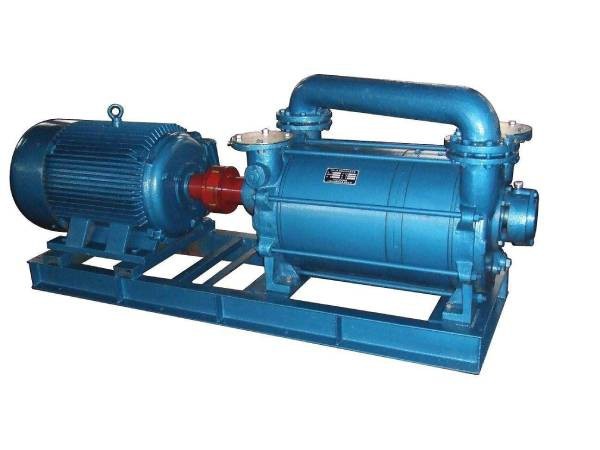
Firstly,it is necessary to clarify the relative positional relationship of each component.Reasonable layout of impellers,pump bodies,suction ports,exhaust ports,etc.is required on the drawings.Generally speaking,eccentric installation inside the pump body should be emphasized.Because the eccentric position of the impeller has a fundamental impact on the working principle of the entire water ring vacuum pump,it directly determines the formation of the crescent shaped space between the impeller and the water ring,as well as the periodic variation of the small chamber volume.When drawing the
Schematic diagram of water ring vacuum pump of the water ring vacuum pump,it should be clearly marked.
The impeller should protrude from the blade and hub parts,and the number,shape,and inclination angle of the blades need to be accurately drawn.Because the number of blades affects the number of small chambers,which in turn is related to the amount of gas inhaled;The shape and inclination angle of the blades affect the flow state of gas in the small cavity and the force exerted on water and gas by the impeller during rotation.The Schematic diagram of water ring vacuum pump of the water ring vacuum pump also needs to clearly express the tangential position between the hub and the water ring in the diagram,which helps to understand the interaction relationship between the impeller and the water ring.
Label the components and areas involved in the suction and exhaust processes.For example,marking the words"suction"and arrows indicating the direction of intake at the suction port,suction chamber,etc.,accurately displays where the gas is sucked in during the rotation of the impeller,and the path through which the gas flows during the change of small chamber volume.For the exhaust process,it is also necessary to label the exhaust port,exhaust direction,and actual exhaust process,such as when the volume of the small chamber changes during compression and the gas begins to be discharged.

Mark the key positions involving changes in the volume of the small chamber,such as marking cross-sections at different locations.For these cross-sectional positions,briefly describe whether the volume state of the small chamber at this position is larger or smaller,and how the pressure changes,in order to better understand the working principle of suction,compression,and exhaust based on changes in the volume of the small chamber from the diagram.
Auxiliary small graphics or explanations can be added to the blank space next to or inside the Schematic diagram of water ring vacuum pump of the water ring vacuum pump to deepen the understanding of the principle.For example,when illustrating the rotation of the impeller and changes in the volume of the small chamber,a brief diagram of the impeller rotation can be drawn next to it,clearly indicating whether the volume of the small chamber is larger or smaller when the impeller rotates at a certain angle.This auxiliary graphic helps to more intuitively understand the dynamic changes during the working process.In addition,for some complex principle concepts,such as assisting the exhaust valve to eliminate the phenomenon of over compression and under compression,a short explanatory text can be added next to it and a graphic diagram can be used to illustrate the flow of gas when the exhaust pressure is too high or too low.

 Address:Zibo, Shandong
 WhatsApp:+8615805335335
 Wechat: +8615805335335
  E-mail:zs@sdsmachinery.com